As a final year student we need to design a catalytic isomerization unit that effectively rises the octane number by isomerization of n-butane, n-pentane and n-hexane into their respective isomers. I was responsible for the design of the reactor, this was probably the most difficult thing I have done in engineering since I started the course. It took a lot of hard work, but in return I am most certainly a much better engineer.... (P.S. The most difficult part of the project was finding the correct reaction kinetics, and just a note to the reader, I do not fully trust the kinetics that was used in this design.)
3.1 Reactions and Kinetics
n-Butane

3.1 Reactions and Kinetics
n-Butane
In a process such as the Penex process where carbon strings from C4-C6 are present a large amount of possible reactions can take place in the form of isomerisation and cracking. We will begin by considering the short straight chains and their reaction and kinetics first then move to the cyclic molecules and their reactions.
Consider the following n-Butane reaction:
This reaction is very simple and has only one isomerization product. From research done by Bagajewicz the following reaction kinetics of butane over a chlorinated platinum alumina catalyst was obtained (Bagajewicz, 2007) .
Bagajewicz used the following units and operating conditions:
- Phase of reactions: gas (p.16)*
*he states pentanes and hexanes can isomerize in both the gas and liquid phases
- Butane is usually reacted in a separate unit than pentane and hexane (not always)
- Reactor temperature: 200°F-400°F (93°C-204°C)
- Pressure: 250psig-500psig (1723.689kPa- 3447.378kPa)
- H2:HC: 0.1-4 (hydrogen to hydrocarbon ratio)
- LHSV: 1-2h (LHSV = Reactant Liquid Flow Rate/Reactor Volume)
- His model predicts the weight % of isomerate
- Requires inputs of: H2 flow in (g/s), wt% of feed stream, temperature
- He then uses the wt% and the Antione equation* to give the partial pressures
*Antione equation:
· Partial pressures are to be found by using the inlet mole fractions and the unit operating pressure
· He used a universal gas constant as 0.0820575 atm*L/mol*K
· The Arrhenius* equation is then used to find the dependence of the rate constant
*Arrhenius equation is given as:
· Using the given activation and frequency factors for the Arrhenius equation
Arhenius Equation Constants
| |||
E(J/mol)
|
A
|
dependancy factor (atm/s)
| |
k1
|
58615
|
3953058
|
0.2297
|
k2
|
66989
|
25140735
|
0.1351
|
R
|
0.082058
|
8.314
| |
T
|
423.15
| ||
 |
| Equation 1: Rate for n-butane |
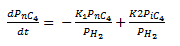
- ·The rate for butane can then be modelled as seen in equation 1. With K1 and K2 as the forward and reverse reactions respectively.
· The following differential equation was used to determine the equilibrium
Bagajewicz uses the following acronyms:
CRU: Catalytic Reforming Unit
LP: Linear Programming
The Simulation used in Polymath was:
d(Pnc4)/d(t)= (-K14*(Pnc4))+K24*(Pic4)
Pnc4(0)=0.187168148
PH2=13.83478093
Pic4=0.07260343+(0.187168148-Pnc4)
XnC4=(0.187168148-Pnc4)/0.187168148
K14=A14*exp(-E14/(R*T))
K24=A24*exp(-E24/(R*T))
A14=3953058
A24=25140735
E14=58615
E24=66989
R=8.314
T=453.15
t(0)=0
t(f)=60
This resulted in the following concentration curve:
 |
| n-butane concentration vs time curve |
The conversion was found to be: xnC4=0.46
This is accurate when compared to literature where it can be seen that very little n-Pentanes isomerise in the Penex process using platinum alumina catalyst. From plant data it is found that xnC4=0.06 (Meyer, 2006) .
n-Pentane

Hexane
(Kinyakin, Glushachenkova, Borutskii, Shuvalov, & Pisarenko, 2008) used the following units and operating conditions
MethylCycloPentane
Reactor design
Reactor 1
Reactor 2
Physical properties of catalyst
Determining the mass catalyst
Determining pressure drop over each reactor
Pressure vessel design
Catalyst support
Insulation
Bibliography
n-Pentane
The reaction and kinetics of n-Pentane is also relatively simple because only one isomer exists and other side reactions are neglect able, the reaction is as follows:
Bagajewicz also studied the reaction of pentane over the chlorinated alumina catalyst, and found the kinetics to be:
 |
Equation 2: Rate equation for nC5
|
With Keq:
 |
Equation 3: K equilibrium
|
This was also modelled in polymath in a similar manner as n-butane and a conversion of xnC5=0.79 was found which is comparable to literature conversions which are found to be xnC5=0.603. The Henry coefficient was used to get the concentration from the partial pressure of Hydrogen (Sander, 1999) .
The code used in Polymath was as follows:
Keq=exp(Rg*((1861/T)-1.299))
Rg = 0.0820575
V = 7160.261/60
d(CnC5)/d(t) = (-(K25*((CnC5/CH2)^0.125) - 0.0000197*t))*(Keq*CnC5-(Keq+1)*CiC5)
K25=A25*exp(-E25/(R*T))
A25=4024
E25=42287
nt=1157.775*1000/3600
CnC5(0) = 0.348257696
CH2 = 0.440423
CiC5 = 0.308115365 + (0.348257696-CnC5)
XnC5 = (0.418830625-CnC5)/0.418830625
The following curve was obtained:
 |
Figure 2: Concentration curve of nC5
|
Hexane
n-Hexane is very difficult to model because it has such a large amount of isomerization products, the Following reactions take place:
 |
Figure 3: n-Hexane reactions
|
The three groups as indicated in Figure 3 can be used to determine the conversion of n-hexane, the following set of kinetic Equation 4 was used:
 |
Equation 4: Simple reaction kinetics of n-Hexane
|
Equation 4 was programmed into Polymath and the results can be seen in Figure 6:
 |
Figure 4: n-Hexane concentration curve
|
The following kinetic equations were used to be modelled in Polymath (Kinyakin, Glushachenkova, Borutskii, Shuvalov, & Pisarenko, 2008) :
 |
Figure 5: Netto reaction kinetics of n-hexane
|
This reaction kinetics was used to determine the net conversion of the each component the following was done in Polymath:
d(CA)/d(t) = -k1*CA + k2*(C2MP+C3MP+C23DMB)
CA(0) = 0.001452
CA0 =0.001452
d(XA)/d(t) = ( (-k1*CA + k2*(C2MP+C3MP+C23DMB)))/CA0
XA(0) = 0
d(C2MP)/d(t) = k1*CA/(1+K1+K2) - C2MP*(k2+k3)
C2MP(0) = 0.000907
C2MP0 = 0.000907
d(X2MP)/d(t) = ((k1*CA/(1+K1+K2) - C2MP*(k2+k3)))/C2MP0
X2MP(0) = 0
d(C3MP)/d(t) = (K1*k1*CA)/(1+K1+K2) - C3MP*(k2+k3)
C3MP(0) = 0.000726
C3MP0 = 0.000726
d(X3MP)/d(t) = ((k1*CA/(1+K1+K2) - C3MP*(k2+k3)))/C3MP0
X3MP(0) = 0
d(C23DMB)/d(t) = (K2*k1*CA)/(1+K1+K2) - C23DMB*(k2+k3)
C23DMB(0) = 0.000136
C23DMB0 = 0.000136
d(X23DMB)/d(t) = (((K2*k1*CA)/(1+K1+K2) - C23DMB*(k2+k3)))/C23DMB0
X23DMB(0) = 0
d(C22DMB)/d(t) = k3*(C2MP+C3MP+C23DMB)
C22DMB(0) = 0.0000454
t(0) = 0
t(f) = 4
k1=6.2085
k2=3.5384
k3=0.620
K1=0.667
K2=0.497
The results can be seen in Figure 6:
 |
Figure 6: n-Hexane concentration curves
|
This model was tested with the data from the publisher and the model fitted perfectly. The only changes made for fitting our model was to change the initial concentrations. This results are the net conversion of the respective components. This data was used to find the time at which 74% of the n-hexane was converted to its different isomers. This time was then used to model the single forward reactions that will be used in Aspen. The forward reactions can be seen in Figure 7:
 |
Figure 7: Forward reactions of all straight chain C6 components
|
These reactions were also modelled in Polymath:
CnC60 = 0.001452
d(CnC61)/d(t) = -a
CnC61(0) = 0.001452
#d(XnC6)/d(t) = (-a-CnC60)/CnC60
#XnC6(0) = 0
d(CnC62)/d(t) = -b
CnC62(0) = 0.001452
d(CnC63)/d(t) = -c
CnC63(0) = 0.001452
d(C2MP1)/d(t) =-d
C2MP1(0) = 0.000907
d(C3MP1)/d(t) = -e
C3MP1(0) = 0.000726
d(C23DMB1)/d(t) = -f
C23DMB1(0) = 0.000136
d(C2MP2)/d(t) =-g
C2MP2(0) = 0.000907
d(C3MP2)/d(t) = -h
C3MP2(0) = 0.000726
d(C23DMB2)/d(t) = - i
C23DMB2(0) = 0.000136
t(0) = 0
z(f) = 0.474
k1 = 6.2085
k2 = 3.5384
k3 = 0.6200
K1 = 0.667
K2 = 0.49
a = (k1*CnC61)/(1+K1+K2)
b = (k1*K1*CnC61)/(1+K1+K2)
c = (k1*K2*CnC61)/(1+K1+K2)
d = k2*C2MP1
e = k2*C3MP1
f = k2*C23DMB1
g = k3*C2MP1
h = k3*C3MP1
i = k3*C23DMB1
The results can be seen in Figure 8:
 |
Figure 8: Concetration curves of individual reactions
|
This data was used to determine the conversion of each reaction by multiplying it with the conversion of the complete conversion found in figure 7.
- · Experiments were carried out at: T = 100-480°C & P = 0.6 – 5 MPa
- · Volumetric flow rate: Vvol: 1.5-6h-1
- · τ = 0.667 – 0.1667 h (residence time)
MethylCycloPentane
The reaction tree for MCP is as follows:
 |
Figure 9: Reaction tree for Methylcyclopentane
|
Donnis found that the rate limiting step in this reaction is for MCP= to a compound with cyclohexane structure. Donnis also found that the reaction of CH→Benzene is very fast and is thus not rate limiting and will not be used for reactor sizing.
All experimental data are correlated by the following equation:
 |
Equation 5: Reaction rate of formation of CH and Benzene
|
· r : reactionrate (gmole/h.gcat)
· k0 : preexponential factor
· Eobs : apparent energy of activation (kcal/gmol)
· R : Universal gas constant (1.987*10^-3 kcal/gmol K)
· T : Temperature (K)
· px : Partial pressure (atm)
The formation of CH= is generally not detected. The step from MCP= to a cyclohexane structure is considered to be the rate limiting step.
Reactor design
Reactor 1
It is safe to assume that the greater part of the reaction regarding the cyclic and aromatic compounds occur in the first reactor where the temperatures are chosen to be higher, because the energy absorption of aromatic and naphthenic components are significantly higher and have an adverse effect on the slightly exothermic nC5 and nC6 isomerization reactions (Polanec, Bionda, Adžamić, & Mužic, 2012) . Another reason to believe that minimal reactions on n-pentane and n-hexane occur in the first reaction is because Polanec et al. observed that the presence of benzene in the reaction mixture greatly affected the reaction product conversion of n-hexane to isomer product, it was found when 4wt% of benzene was present in the reaction mixture compared to pure n-hexane, that isomerization products was reduced by 50-60% depending on the temperature of the reactor (130-170°C).
Reactor 2
In reactor two the greater part of the n-hexane is converted to iso hexane product this is also the rate limiting reaction between C5 and C6 reactions (Polanec, Bionda, Adžamić, & Mužic, 2012) . The formation of 2,2-dimethylpentane from 2MP, 3MP and 23DMB is the slowest of all the reactions concerning C5 /C6 reactions and is thus rate limiting and will be used for control and reactor design purposes, 22DMB also has the highest activation energy (Polanec, Bionda, Adžamić, & Mužic, 2012) .
Physical properties of catalyst
Catalyst used (Liaoning Haitai Sci-Tech Development Co, 2013) : HT-15
 |
Figure 10: Isomerization catalyst HT-15
|
Platinum,%
|
0.32±0.02
|
Surface area, m2/g
|
400
|
Strength, N/particle
|
80
|
Bulk density, kg/L
|
0.75
|
Appearance
|
Cylinder
|
Diameter, mm
|
2–2.2
|
Length,mm
|
3-8
|
Bed Porosity
|
0.34
|
Determining the mass catalyst
The reaction kinetics for n-hexane was used for the sizing of the reactor. The reaction rate was given as:
 |
Equation 6: Reaction rate for n-hexane
|
This reaction rates units are then found to be: molA/(l*h)
To convert this rate into a –r’A the following relation needs to be used:
 |
Equation 7: Reaction rate for determining the catalyst weight
|
With, ρb, being the bulk density of the catalyst. Since the equation for –rA is now known the weight of the catalyst can be determined with the following relation.
 |
Equation 8: Catalyst weight differential equation
|
With W being the catalyst weight and XA the conversion. By using equation 6 and the relation found in equation 7 a graph of -1/r’A VS. XA can be drawn. The following curve was obtained from polymath:
 |
Figure 11: 1/-rA vs XA curve for determining catalyst weight
|
This curve is then integrated to obtain the mass of catalyst needed for the reactor to operate. It was found that 3371914 kg of catalyst is needed for the reactor. From this a reactor volume can be determined by dividing the catalyst weight by the bulk volume of the catalyst. It was found that a reactor volume of 4495m3 is needed. It was decided to us six reactors in series with height to diameter ratio if 7.6:1 for this design. The dimensions of each reactor will then be:
Diameter
|
5m
|
Height
|
38m
|
Determining pressure drop over each reactor
Pressure drop is a function of superficial velocity, bed porosity, shape factor of the catalyst particles and particle diameter. The shape factor for cylindrical particles needs to be determined firstly using Equation 9.
 |
A value of 1.34 was calculated. A diameter of a sphere of equal volume as the cylinder was then needed to be obtained. Basic volumetric calculations were used to determine a spherical diameter of 2.9 mm that would be used for further pressure drop calculations. The Reynolds number was calculated next using Equation 10:
 |
Equation 10: Reynolds number
|
 |
|
|
A pressure drop of 1.02 atm per reactor was calculated.
Pressure vessel design
The design will be based on a typical pressure vessel as shown below. The only main difference from the design below is that there will be an inlet at the top of the reactor and an outlet at the bottom.
 |
Figure 12: Typical pressure vessel
|
Pressure
|
32 atm
|
Temperature
|
195°C (max)
|
Materials used:
|
-
|
Shell
| |
Head
|
SA-181 Gr. I
|
Nozzles
|
SA-106 Gr. B
|
The following design equation was used for the design of the shell (Livingston & Scavuzzo, 2000) :
 |
Equation 12: Shell thickness
|
The thickness of the walls was found to be: 72 mm
The hemispherical head thickness is determined by using the following formula (Livingston & Scavuzzo, 2000) :
 |
Equation 13: Hemisphere thickness
|
The same equation was used to determine the nozzle properties, a 20in ID pipe was chosen for the inlet and outlet of the reactor as this is a standard produced pipe, from the calculations it was found that the inlet pipe had to have a 0.371 in or 9.42mm thick wall, a standard pipe of wall thickness 0.375 is produced, and will thus be used for this reactor (Meis-Klütz, 2007) .
At each opening the structure needs to be reinforced as shown in the figure below (Livingston & Scavuzzo, 2000) .
 |
Figure 13: Opening reinforcement requirements
|
The areas where pieces of the vessel are removed to insert the nozzles are weakened and stress concentrations exist at the opening edge and decrease radially (Livingston & Scavuzzo, 2000) . To avoid failure or rapture at the opening the area needs to be reinforced, different ways exist to reinforce a vessel at the openings: (1) increase the pressure vessel wall thickness (2) increase the watt thickness of the nozzle (3) use a combination of (1) and (2).
The following equations where used to calculate the required reinforcements, option (1) was chosen for economical and ease of construction purposes.
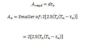 |
Equation 14: Required Area for reinforcements
|
 |
Equation 15: Design parameter for nozzle reinforcements
|
It was found that the minimum wall thickness for the reinforcements was found to be: 111mm for a distance of the diameter of the pipe from the base of the nozzle.
A welding neck flange was chosen for this operation as these types of flanges are considered to be the best for high pressure conditions ( IHS GlobalSpec) .
 |
Figure 14: Welding neck Flange
|
Catalyst support
Two catalyst support structures will be present, because of the very tall design, one in the middle of the reactor and one at the bottom. The middle support structure will include a second redistribution tray. A side by side construction support grid will be used, the side by side construction is depicted below, includes an additional rectangular plate welded to the screen supports which ensures a very strong structure that is resistant to surges and can operate at extreme loads (Johnsonn Screens) .
 |
Figure 15: Side by Side support grid construction
|
 |
Figure 16: Typical support grid planned to be used
|
The complete support grid is shown in the figure above, this support grid includes a manhole for inspections and when the catalyst needs to be inserted or replaced (Johnsonn Screens) .
On top of this support grid ceramic balls will be placed two different sizes will be placed on top of another. First larger balls, then the smaller balls, a typical arrangement looks as follows.
 |
Figure 17: Catalyst support Media
|
 |
Figure 18: Catalyst support in reactor
|
In the reactor the support media will be placed as shown above. The Ceramic balls used are provided by Christy Catalytics and the product to be used is titled: PROX-SVERS® T-38 INERT CATALYST BED SUPPORT BALLS (Christ Catalytics, 2013) . On the bottom 100mm of ½” balls will be used and on top of them 100mm of ¼” balls will be placed. The catalyst support media has the following physical properties (Christ Catalytics, 2013) . The HT-15 Catalyst is then sandwiched between two layers of catalyst support material, the top layer of catalyst support material will be 150mm of ½” catalyst support media (HAT International, 2008) .
 |
Table 3: Catalyst Support media physical properties
|
On top of the catalyst support balls, a bubble cap tray will distribute the inlet gas. The figure below illustrates a typical bubble cap tray that will be used in this reactor. Beneath the support grid in the middle of the reactor a redistributor tray will be placed.
 |
Figure 19: Redistribution tray
|
At the bottom of the reactor there will not be any support grids across the whole reactor but only an outlet collector will be placed at the exit (Johnsonn Screens) . ½” ceramic balls will be placed on the bottom of the reactor till the outlet collector is covered, on top of that 100mm of ¼” ceramic balls will be placed on top of that. The absence of a bottom support grid will make it easier to remove the catalyst.
 |
Figure 20: Bubble cap tray
|
Insulation
Industrial insulation blanket, Thermafiber®, was chosen for insulation in this design; 1” of Thermafiber delivers enough insulation in order to have an external temperature of only 21°C when a maximum internal reactor temperature of 195°C is anticipated (Thermafiber, 2012) . One-dimensional conduction was used to determine the insulation thickness required to achieve an external temperature that is not harmful to humans. Equation 16 for heat transfer was used (Incropera, Dewitt, Bergman, & Lavine, 2005) :
 |
Equation 16: Heat transfer rate for composite watt system
|
Equation 16 was used to determine a heat transfer rate for a system with no insulation; r3 was then solved by for an external reactor temperature of 35°C, it was found that 23.2 mm of insulation would be needed. Thermafiber only provides insulation blankets in thicknesses ranging from 1.5”-7”, 1.5” being 38.1 mm, provides more insulation than required and will thus be used for insulation in this project.
 |
Figure 21: Reactor and Insulation diagram
|
Bibliography
IHS GlobalSpec. (n.d.). Learn More: Globalspec. Retrieved September 15, 2013, from IHS GlobalSpec: http://www.globalspec.com/learnmore/flow_control_fluid_transfer/pipe_tubing_hose_fittings_accessories/pipe_flanges
Liaoning Haitai Sci-Tech Development Co. (2013, Augustus 12). Retrieved September 13, 2013, from Liaoning Haitai Sci-Tech Development Co: http://chinacatalyst.en.alibaba.com/
Bagajewicz, M. J. (2007). Refinery Operations Planning.
Christ Catalytics. (2013, June 27). ChristyCatalytics. Retrieved Septermber 2013, 2013, from Christy Catalytics: http://www.christycatalytics.com/Portals/55271/docs/T-38_PROX-SVERS_DATA%20SHEET.pdf
Donnis, B. B. (1976). Platinum/Alumina Catalysts in Reforming Methylcyclopentane. industrial Engineering Chemistry, 254-258.
HAT International. (2008, January 10). HAT International. Retrieved September 15, 2013, from HAT International: http://www.hatltd.com/hosted/55000702/home.nsf/396e036940cdfb7a802571280074ad47/ba190ad09a9b590b80257bb7004f18e9/$FILE/DS-RI%20Reactor%20Internals.pdf
Incropera, F. P., Dewitt, D. P., Bergman, T. L., & Lavine, A. S. (2005). Fundamentals of heat and mass transfer. John Wiley & Sons.
Johnsonn Screens. (n.d.). Johnson screens. Retrieved September 15, 2013, from Johnson Screens: http://www.johnsonscreens.com/sites/default/files/6/703/Internals%20for%20Down%20Flow%20Reactors.pdf
Kinyakin, A., Glushachenkova, E., Borutskii, P., Shuvalov, A., & Pisarenko, Y. (2008). Kinetics of the Low-Temperature Isomerization of n-Hexane on the NIP-3A Catalyst in an Isothermal Flow Reactor. Theoretical Foundations of Chemical Engineering, 815–821.
Livingston, E., & Scavuzzo, R. J. (2000). The engineering Handbook. CRC Press LLC.
Meis-Klütz, A. (2007, November 30). Tube & Pipe Sizes 5th edition. Technitube Rohrenwerke GMBH. Daun, Germany: Julius-Saxler-Straße 7.
Meyer, R. A. (2006). Handbook of Petroleum Refining Processes. McGrawHill.
Polanec, D., Bionda, K. S., Adžamić, Z., & Mužic, M. (2012). INFLUENCE OF BENZENE ON THE PROCESS OF n-HEXANE ISOMERIZATION ON Pt/SO4. Original scientific paper.
Sander, R. (1999). Compilation of Henry’s Law Constants for Inorganic and Organic Species of Potential Importance in Environmental Chemistry. Mainz: Max-Planck Institute of Chemistry.
Schabort, C., & A.Visser. (2013). C5/C6 Isomerisation Unit Process Design 2013. CRS: Plant Design and Evaluation, North-West University, Potchefstroom.
Sinnot, R. K. (1999). Chemical Enginering. Burlington: Butterworth Heineman.
Thermafiber. (2012). Thermafiber. Retrieved 09 25, 2013, from Thermafiber: http://www.thermafiber.com/Portals/0/pdf/industrial%20blanket.pdf
UOP LLC. (2003). Gasoline Upgrading. Somerset West.
Yasakova, E., & Sitdikova, A. (2010). TENDENCY OF ISOMERIZATION PROCESS DEVELOPMENT IN RUSSIA AND FOREIGN COUNTRIES. Ufa State Petroleum Technological University.
Zhang, W., Thompson, K. E., Reed, A. H., & Beenken, L. (2006, September 23). Relationship between packing structure and porosity in fixed beds of equilateral cylindrical particles. Chemical Engineering Science, pp. 8060-8074.
Trupply offers wide variety of metal flanges in carbon steel, stainless steel and nickel alloy. We can also provide special flanges such as long weld neck flange, special material request and high-yield pipe flanges.
ReplyDeleteWeld neck flange